Chart your course
Sailboat Alternator Not Charging
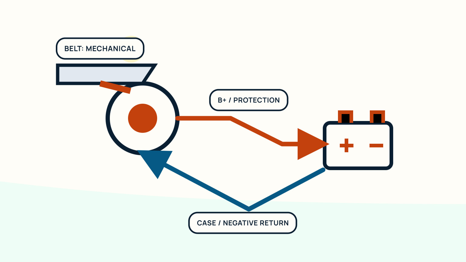
Quick answer
The short version
When a sailboat alternator is not charging, start by protecting the boat and recording the evidence. Note panel alarms, battery monitor behaviour, engine speed, recent electrical changes, smell, sound, and whether the problem appeared suddenly. With the engine stopped where access requires it, inspect the belt, alternator mount, visible cables, terminals, and damaged insulation. Do not guess a universal charging voltage or disconnect cables on a running engine. The correct test points and values depend on the alternator, regulator, battery chemistry, wiring, and engine manual. Heat, smoke, arcing, or a burnt odour ends owner testing and calls for qualified electrical service.
“Not charging” can describe several observations: a warning lamp remains on, a monitor shows no rise, the bank continues discharging, or charging starts and stops. None identifies the failed component alone. Treat the system as a path from mechanical drive through alternator and regulation to wiring and batteries. Knowing your battery switch's control states helps, while this process avoids bypassing protection or turning an observation into a diagnosis.
Make the situation safe
First confirm that losing charge is not creating a more immediate navigation or communication problem. Reduce nonessential loads if the boat's procedures call for it, preserve power for essential equipment, and choose a safe place to investigate. Do not work beside moving belts or hot machinery.
Before opening the engine space, note any warning lamp, alarm, monitor screen, odour, and sound. Then stop the engine according to its procedure and allow safe access. Ventilate. Remove jewellery and keep conductive tools controlled around batteries and high-current terminals. Use the maker's isolation sequence before touching connections.
Stop immediately for smoke, heat, arcing, melted insulation, loose high-current hardware, battery damage, or a strong burnt smell. These findings need an electrician or engine technician, not another start to see whether the symptom repeats.
Write down the battery state before changing loads or switches. If shore power, solar, wind, or another charger is active, the monitor may show combined behaviour that masks the alternator. Isolate or account for other sources only through their procedures. Tell crew that the engine may not restart before stopping it during a passage. If safe investigation must wait, preserve the current state and arrange a berth or assistance. The best electrical diagnosis is not worth creating a manoeuvring problem or leaving the boat without communications.
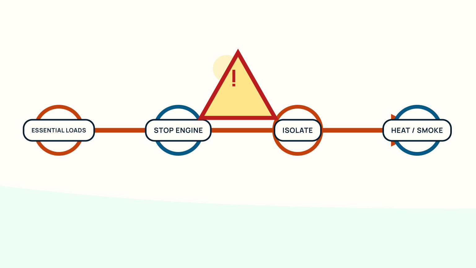
Observe the charging path
The engine drives the alternator through a belt or another model-specific drive. The alternator and regulator control output, which passes through cables, connections, switching and protection where fitted, then reaches the battery system. A monitor samples some part of that arrangement. Draw the installed path before testing.
Record what happens in sequence: panel before start, cranking, idle, a permitted higher speed, and shutdown. Note large loads that were running. Compare only with values and test conditions stated for the installed engine, alternator, regulator, monitor, and battery chemistry.
A monitor reading is evidence from its configured shunt or sensor, not a complete view of every conductor. A charging lamp is also one clue. Wiring changes, shore charging, solar, split charging, or battery-management equipment can alter what you expect to see.
Label each reading by source. “12.4” means little without battery bank, test point, engine speed, load, other chargers, and elapsed time. Capture the monitor screen and the panel together when possible. If charging appears only after increasing speed, or disappears with a particular load, record the repeatable condition instead of declaring the alternator weak. Intermittent behaviour may need a technician to observe the system while operating. Avoid wiggling cables on a live engine to provoke the fault; movement near belts and high-current terminals adds risk and changes evidence.
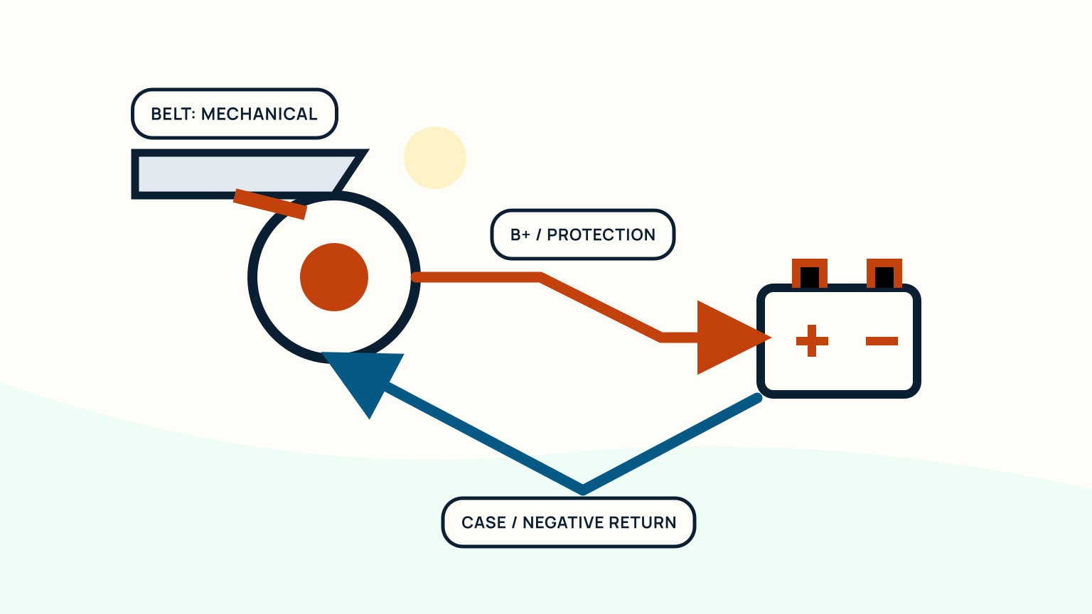
Check simple connections
With the system stopped and isolated as directed, inspect belt condition and obvious tension against the engine manual. Look for glazing, cracks, dust, contamination, or a loose mount. Do not place fingers near a belt while the engine can start. The manual controls adjustment and replacement.
Follow visible output and return connections. Look for looseness, corrosion, chafe, unsupported cable, heat damage, and a connector disturbed by recent work. Check that battery and isolation controls are in the intended operating state. Never tighten or move an unidentified live cable.
Photograph each finding before cleaning or adjustment. A corroded terminal can contribute to resistance, but its appearance does not prove it is the only fault. If the owner manual permits a correction, follow its sequence and torque. Otherwise leave the connection undisturbed for a technician.
Check recent work first. A battery replacement, charger installation, engine service, or cable move may have changed a switch state, disturbed a terminal, or altered monitor configuration. Compare photographs and diagrams from before the work. Do not assume the newest component caused the problem, but use the timeline to focus inspection. If the belt leaves dust, repeatedly loses adjustment, or runs out of line, replacing it alone may hide a mount or pulley issue. Preserve the old part and record its markings for the technician.
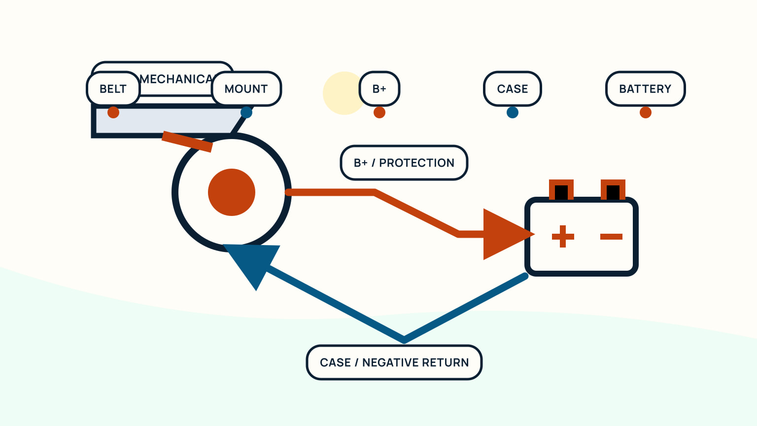
Avoid damaging tests
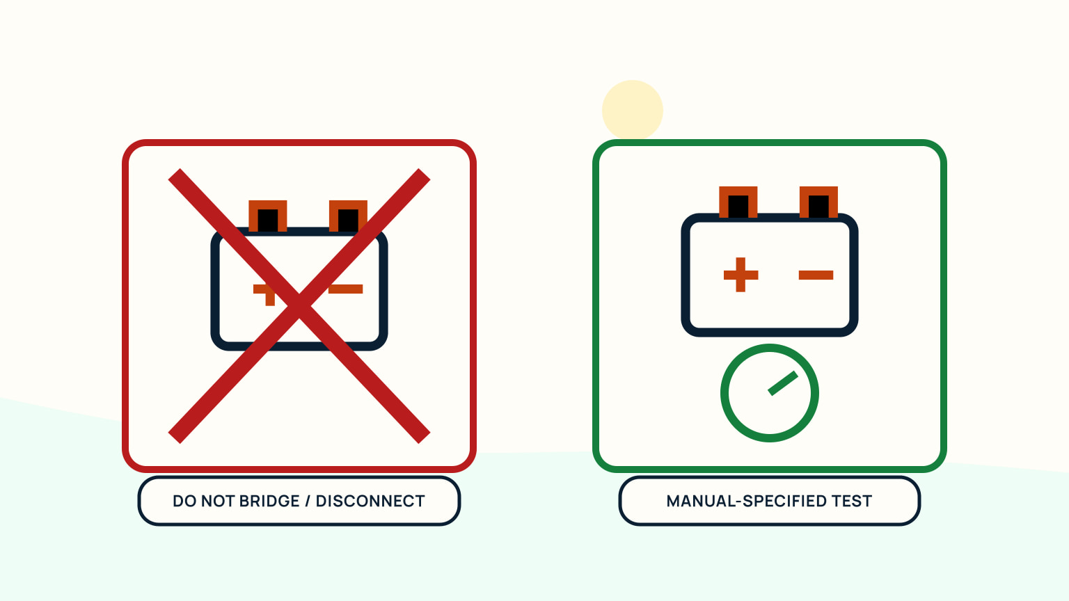
Do not remove an alternator or battery cable while the engine runs. Do not short terminals, bypass a fuse or interlock, substitute a random test point, or apply automotive advice without checking the marine installation. High current can damage equipment and cause fire.
If the manuals specify meter tests, use the exact points, instrument setting, and operating state they require. Establish a sound reference and keep probes away from moving machinery. A measured difference across a cable or connection only means something within the stated test method and circuit state.
Avoid changing several things before retesting. Cleaning a connection, adjusting a belt, changing a switch state, and replacing a battery at once destroys useful evidence. Make one authorized correction, inspect the whole area, restore guards, and repeat the documented check.
Use insulated covers and probe guards where the test procedure calls for live measurement. Secure loose clothing and keep a second person at the controls when an engine-running test is necessary. Define the stop signal before starting. If a value is outside the manual's range, stop and interpret it with the complete circuit rather than repeating the test at progressively riskier points. A qualified marine electrician can measure voltage drop, field control, output, and battery response with the correct instruments and understand how other charging sources interact.
Decide who should repair it
Owner checks can often settle an incorrect switch state, obvious damaged belt, loose visible connector, or poor documentation. Internal alternator faults, regulator diagnosis, high-current rewiring, repeated belt failure, battery-management configuration, and unexplained heating belong with a qualified marine electrician or engine technician.
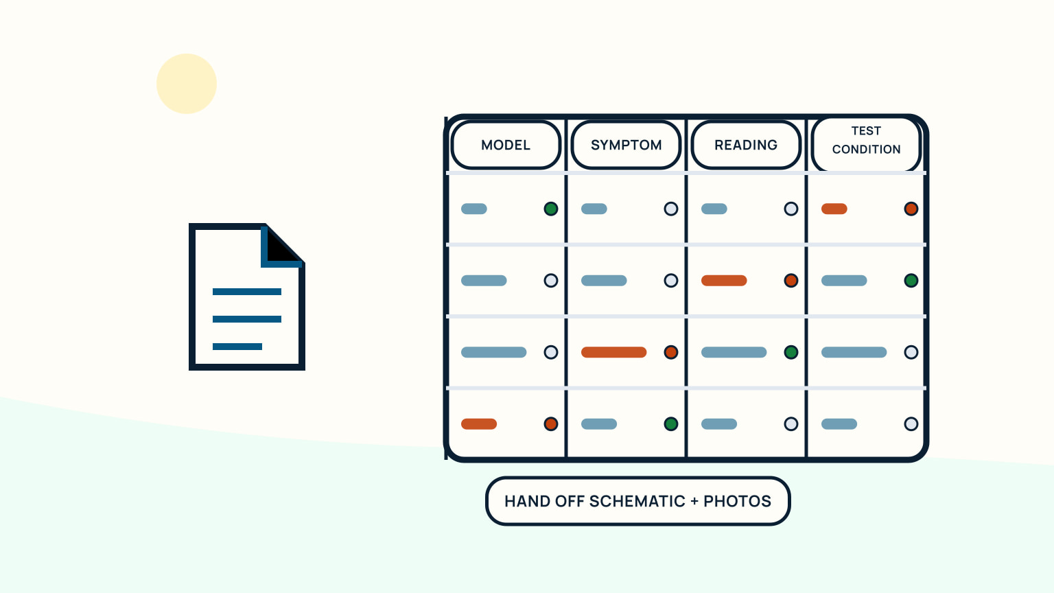
Prepare a useful handoff. Provide engine, alternator, regulator, battery, monitor, and charger models; the installed schematic; recent work; service history; photographs; alarms; and readings with their exact test conditions. State whether the fault is constant, speed-related, load-related, or intermittent.
After repair, obtain the diagnosis, parts, settings, test results, and updated drawing. Put the next check into the maintenance calendar and compare it with the battery maintenance guide. A system returned to service should be documented, guarded, and observed through the maker's complete test.
Ask the technician to identify the failed path and its cause, rather than simply naming the replaced part. A burnt connection may result from looseness, corrosion, unsupported cable, or excessive current. A belt problem may reflect alignment or load. Update cable sizes, protection, regulator settings, and battery configuration on the schematic when they change. Keep the final readings with their test condition so future checks have a genuine baseline. If the repair changes charging behaviour, review shore and renewable charging too; the battery experiences the combined system.
Build a normal charging record after the system is healthy. Capture the same panel and monitor states at start, idle, the maker-approved operating speed, and shutdown with known loads and other charging sources accounted for. Repeat after a few ordinary trips. This baseline makes a later change visible and gives a technician something more useful than a generic expected value. Review it when batteries, regulator settings, alternator, monitor configuration, or cable routing changes, because the old comparison may no longer describe the installed system.
Begin with the exact recorded symptom and the installed charging path. If a safe visual check does not reveal a manual-led correction, stop before improvised testing. SailStarter lessons can help you understand the system diagram and panel language; a qualified technician should resolve high-current, internal, or unclear faults.
Keep that baseline current.
Try it from the lesson
Can you spot the next move?
The engine is idling, the boat is safely secured and the propeller area is clear. What should you confirm before departure?
Why you can trust this guide
. We build each guide from public seamanship and safety sources, then teach the universal principle before any local difference.