Chart your course
Galvanic Isolator vs Isolation Transformer
Quick answer
The short version
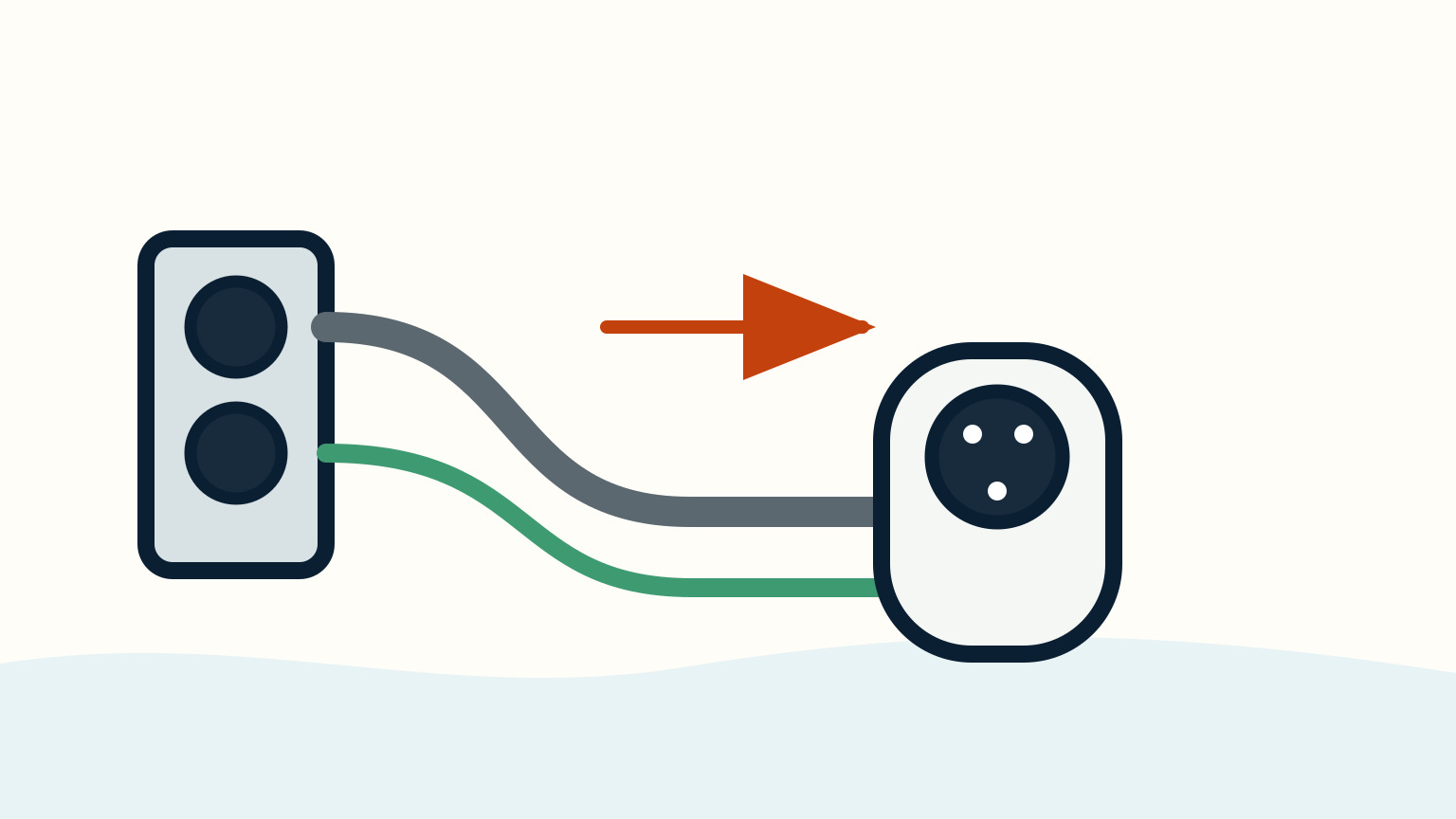
A galvanic isolator and an isolation transformer both address a problem that can begin when a boat connects to shore power: the shore grounding path can link your immersed metals to metals beyond your boat. They are not interchangeable parts. A galvanic isolator is a device in the AC grounding conductor that blocks low-voltage DC galvanic current. An isolation transformer transfers shore power magnetically, separating the boat-side electrical system from the shore-side supply. The right choice depends on the installed shore-power system, the boat, its equipment, and the professional who can inspect and test it.
Start with the useful distinction. A galvanic isolator changes one part of the grounding path. A transformer creates a separated AC supply arrangement. Neither is a casual add-on, and neither replaces good bonding, anodes, dry connections, correct protection, or regular inspection. If you see heat, damage, an unexplained trip, corrosion concern, or wiring you cannot identify, leave the system alone and arrange qualified marine electrical help.
The words are often used in the same conversation because both relate to shore power and corrosion. Their jobs are different enough that a clear question for the electrician will save time: "What is installed now, where is it in the shore-power path, and what evidence says this is the right protection for this boat?"
Start With The Shore-Power Path
Before comparing devices, follow the visible route without opening covers. Shore power begins at a marina supply, runs through a suitable marine cord and the boat inlet, then reaches the installed protection, distribution and AC loads. The grounding conductor is part of that route. It exists for fault protection, so it is not a wire to remove or improvise around when corrosion becomes a worry.
The corrosion question comes from the fact that a grounded shore connection can form an electrical path between the boat's immersed metals and shore-side or neighbouring immersed metals. Different metals and electrolytes can create a small DC galvanic current when a circuit is complete. The result can be loss of protective anode material or damage to a more important underwater component. The path is not visible from a cockpit panel, which is why visual guesses about a green wire or a corroded fitting are not a diagnosis.
Map what you can positively identify: the inlet, cord, shore disconnect, AC panel, charger and any device that is named in the boat documentation. Then mark what is hidden. This simple sketch gives a professional a starting point and stops a common mistake: confusing battery negatives, DC bonding, and AC grounding because they happen to be near one another.
What A Galvanic Isolator Does
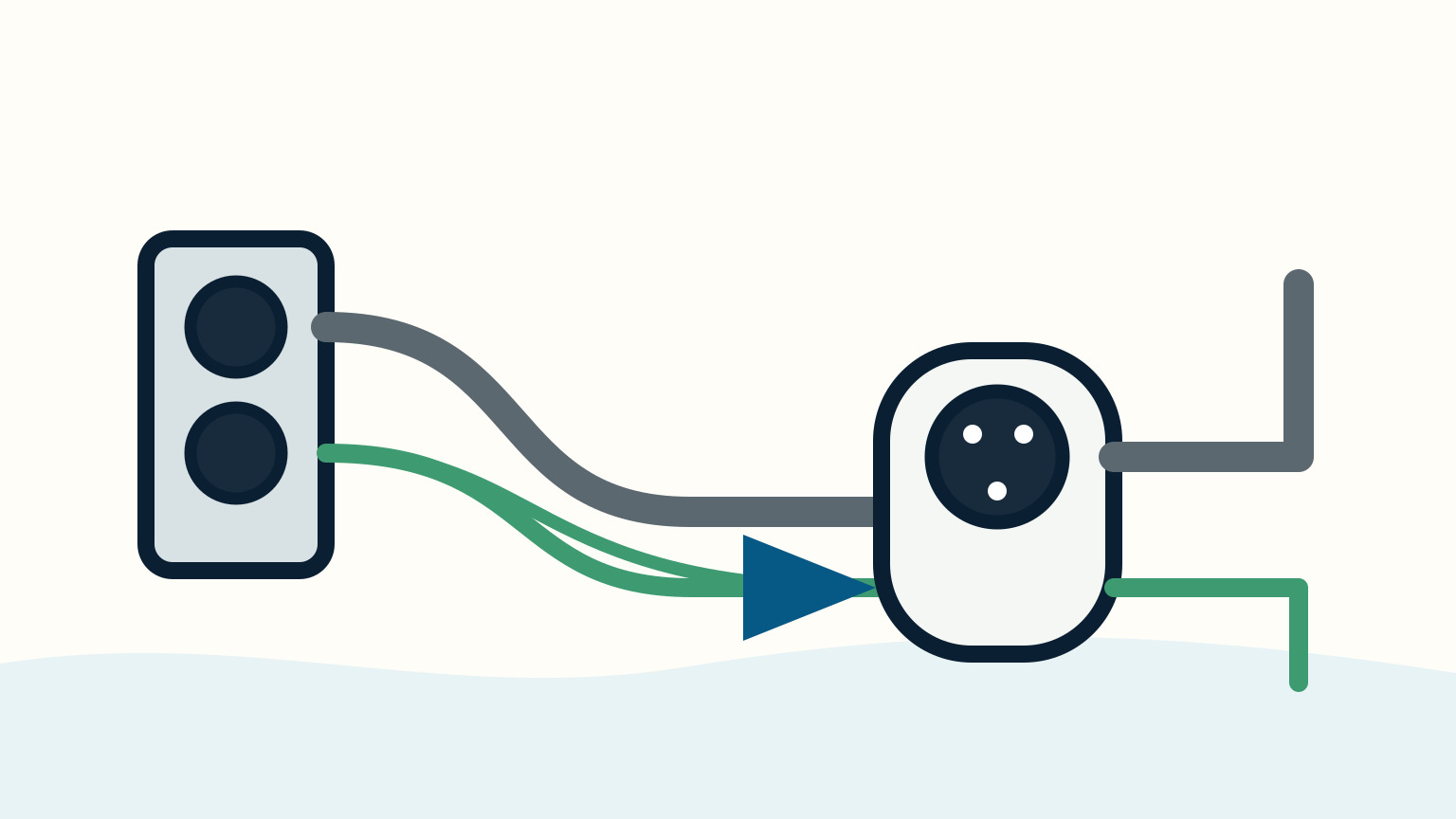
A galvanic isolator belongs in the AC grounding conductor. Its purpose is narrow and specific: block the low-voltage DC galvanic current that can use a shore-ground route, while retaining the appropriate safety behaviour for AC fault conditions in its installed design. It does not make the boat electrically independent of the dock in every respect. It is also not an anode and does not cancel the need to inspect underwater metals and sacrificial anodes.
That narrow job explains its appeal. An isolator can be part of a shore-power corrosion strategy without the size, weight, cost, or installation change associated with a transformer. It may be appropriate for a given vessel, but the decision belongs to the complete system. A unit's rating, fail-safe characteristics, location, installed protection and testing requirements come from its manufacturer, applicable standards and the actual boat.
For an owner, recognition is more useful than touching it. Ask the technician to point out the unit, explain its fault indication if it has one, and record its model and test date. Keep the access route clear and dry. Do not bypass it to "see if that fixes" a corrosion symptom. A bypass can remove a safety function or create a new fault without proving anything about the original concern.
What An Isolation Transformer Does
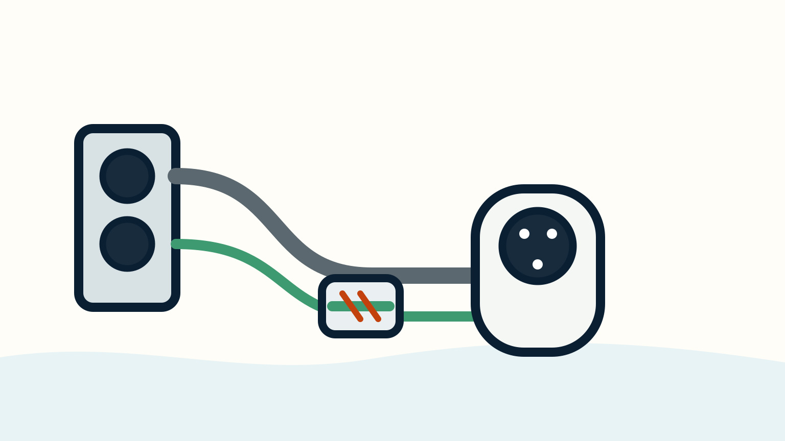
An isolation transformer handles shore-power energy differently. The shore-side winding and boat-side winding transfer energy magnetically rather than through a direct electrical connection. This creates electrical separation between the shore supply and the boat-side system when the transformer is installed as intended. In the corrosion context, that separation prevents the shore grounding path from linking the boat's immersed metals to the shore-side path in the same way.
The difference is physical as well as electrical. A transformer is substantial equipment, with a defined input and output arrangement, protection, enclosure, ventilation and installation requirements. It needs a professional assessment of location, load, supply compatibility and the boat's existing AC system. Treat a transformer as a system choice, not a single black box that can be fitted beside the inlet.
A transformer can offer a clean boundary, yet it does not turn every electrical or corrosion issue into a transformer issue. Damaged shore cords, wet inlets, failing anodes, stray current, loose terminals and incorrect bonding still need their own evidence and repair. Ask what problem the transformer is intended to solve, what remains outside its scope, and which periodic checks preserve the installed arrangement.

Compare The Two Without Oversimplifying
The short comparison is this: a galvanic isolator interrupts low-voltage DC galvanic current in the grounding conductor, while an isolation transformer creates electrical separation between shore and boat-side AC systems. Both are discussed around shore-power corrosion, but they operate at different levels of the system.
Do not turn that into a shopping rule. A smaller device is not automatically inadequate, and a transformer is not automatically required because a boat spends time in a marina. The meaningful questions are about the boat's shore-power arrangement, underwater metals, charging equipment, prior corrosion history, available installation space, service access and applicable requirements. A qualified marine electrician can inspect the system and decide what tests and standards apply.
It helps to separate three jobs that are often blended together. Corrosion protection concerns electrical paths through water and metal. Fault protection concerns safe behaviour when AC equipment fails. General maintenance concerns the condition of cords, inlets, anodes, bonding connections and electrical enclosures. One device may contribute to one job, but no device replaces the other two.
Collect Evidence Before You Choose
Bring records, not assumptions, to the discussion. Photograph external labels and visible equipment without dismantling it. Note whether the boat remains connected to shore power for long periods, what AC loads normally run, and whether any fault indicator or protective device has changed state. Keep a maintenance record for anode inspections, haulouts and any observed corrosion. These observations help a professional separate a routine anode-consumption question from an electrical-system concern.
Stop using shore power and seek help promptly if a cord, plug, inlet or panel is hot, scorched, wet inside, loose, damaged or associated with repeated trips. Burning smell, arcing or an unidentifiable grounding arrangement are not suitable owner experiments. Disconnect through the boat and marina's approved sequence. Do not lift a grounding conductor, use a homemade adapter, or move a suspect cord to another outlet.
When the work is complete, ask for the system description in writing. Record the device model, location, intended function, test method, operating limits and any inspection interval. Update the onboard diagram so a later owner, crew member or electrician does not have to infer the arrangement from a crowded locker. The best outcome is not a mysterious protection box. It is a shore-power system whose boundary and maintenance needs are understood.
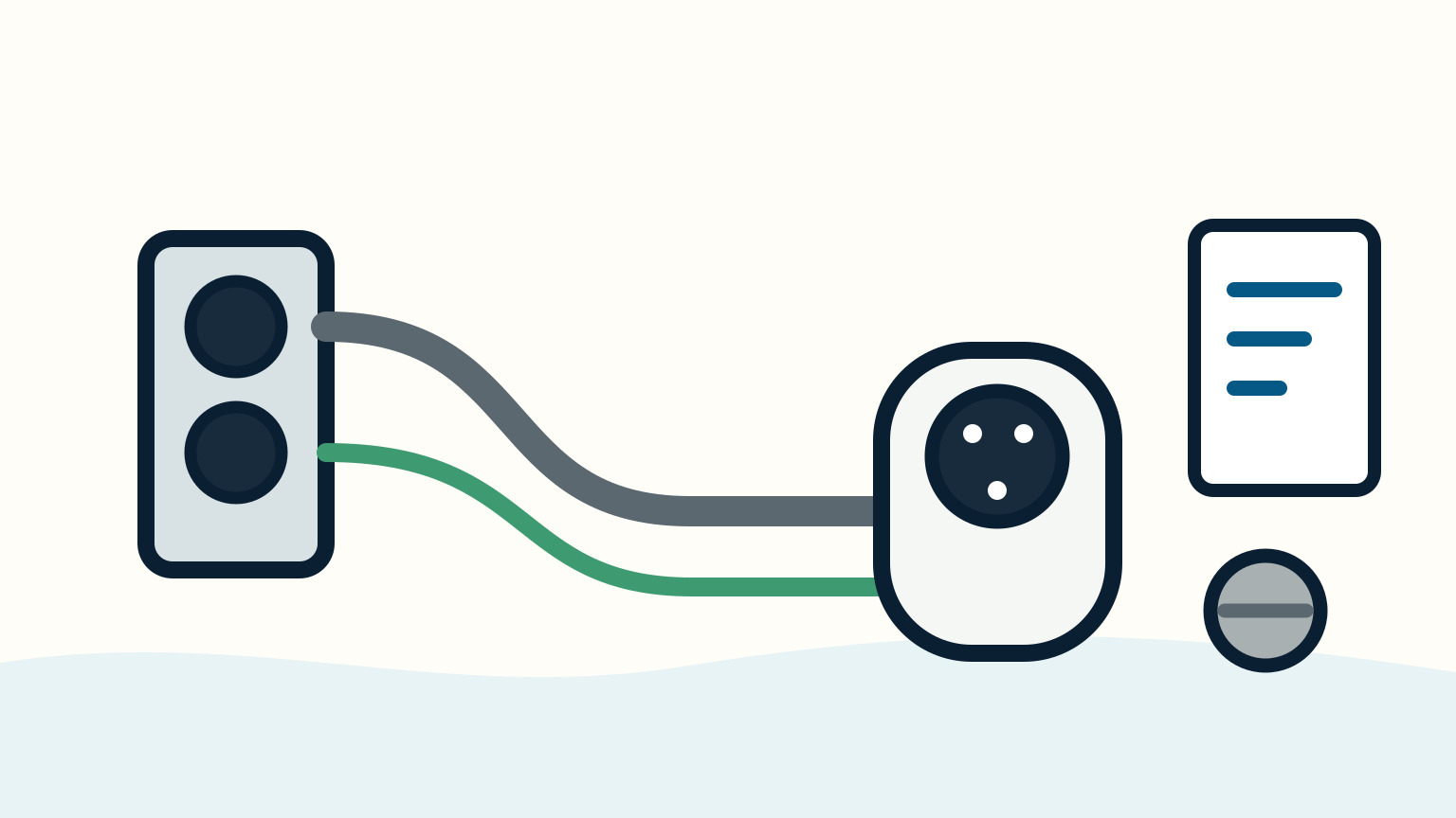
Keep the electrical boundary clear.
Shore power is an AC system that deserves a firm boundary between observation and repair. You can learn the visible path, keep it dry, record labels and notice changes. You should not remove protective covers to chase a suspected corrosion path, modify grounding, or substitute parts based on a forum photo. The installed manuals and current local rules control the exact arrangement.
This boundary is especially useful when several symptoms appear at once. An anode may be worn, a shore cord may look tired, and a battery charger may still appear normal. Those facts do not identify a single cause. Record each one, stop on immediate electrical danger, and let proper inspection decide whether the concern is galvanic corrosion, stray current, an ordinary maintenance interval or a separate fault.
Use the same discipline after a purchase or a refit. Ask for an AC system handover that identifies the disconnect, protection, shore inlet, charger and any galvanic isolator or transformer. A clear handover lets you use the boat confidently without pretending that electrical safety depends on memory or guesswork.
SailStarter's systems lessons can help you read the visible boat layout and record useful observations. Pair this comparison with shore-power basics, sacrificial anodes on sailboats, and sailboat battery maintenance to keep AC safety, corrosion, and DC care in their proper lanes. They do not replace the installed shore-power manual or qualified marine electrical work.
Try it from the lesson
Can you spot the next move?
The engine is idling, the boat is safely secured and the propeller area is clear. What should you confirm before departure?
Why you can trust this guide
. We build each guide from public seamanship and safety sources, then teach the universal principle before any local difference.