Chart your course
How to Find Voltage Drop in a 12-Volt Boat System
Quick answer
The short version
To find voltage drop in a 12-volt boat system, test the circuit while its intended load is operating. Measure voltage at the source, then at the load, and record the difference with the same load state. A large difference means voltage is being lost somewhere in the complete path: positive cable, fuse or breaker, switch, connector, load connection, negative return, or a connection between them. It does not tell you which part failed until you narrow the test safely.
Begin with a clear symptom. A light that dims, a pump that slows, a windlass that struggles, or electronics that restart can all involve voltage drop. They can also involve a weak battery, a charging problem, a failed load or the wrong operating condition. A calm record of battery state, active load, voltage readings and visible condition is more useful than replacing wire because it looks old.
This article is for evidence gathering on an accessible DC circuit. Stop for heat, smoke, melted insulation, damaged battery cases, exposed conductors, water in electrical spaces, or anything you cannot identify. Do not bypass a fuse or breaker, bridge terminals, or alter wire size while diagnosing. Those decisions belong to the installed drawings, manufacturer instructions and a qualified marine electrician.
Understand What The Reading Means
Voltage is the electrical push available to move current. Every conductor and connection has some resistance. When current flows, resistance can leave less voltage available at the far end. That is voltage drop. A reading with the device switched off can look fine because little or no current is flowing. The useful comparison happens under the normal load that reveals the problem.
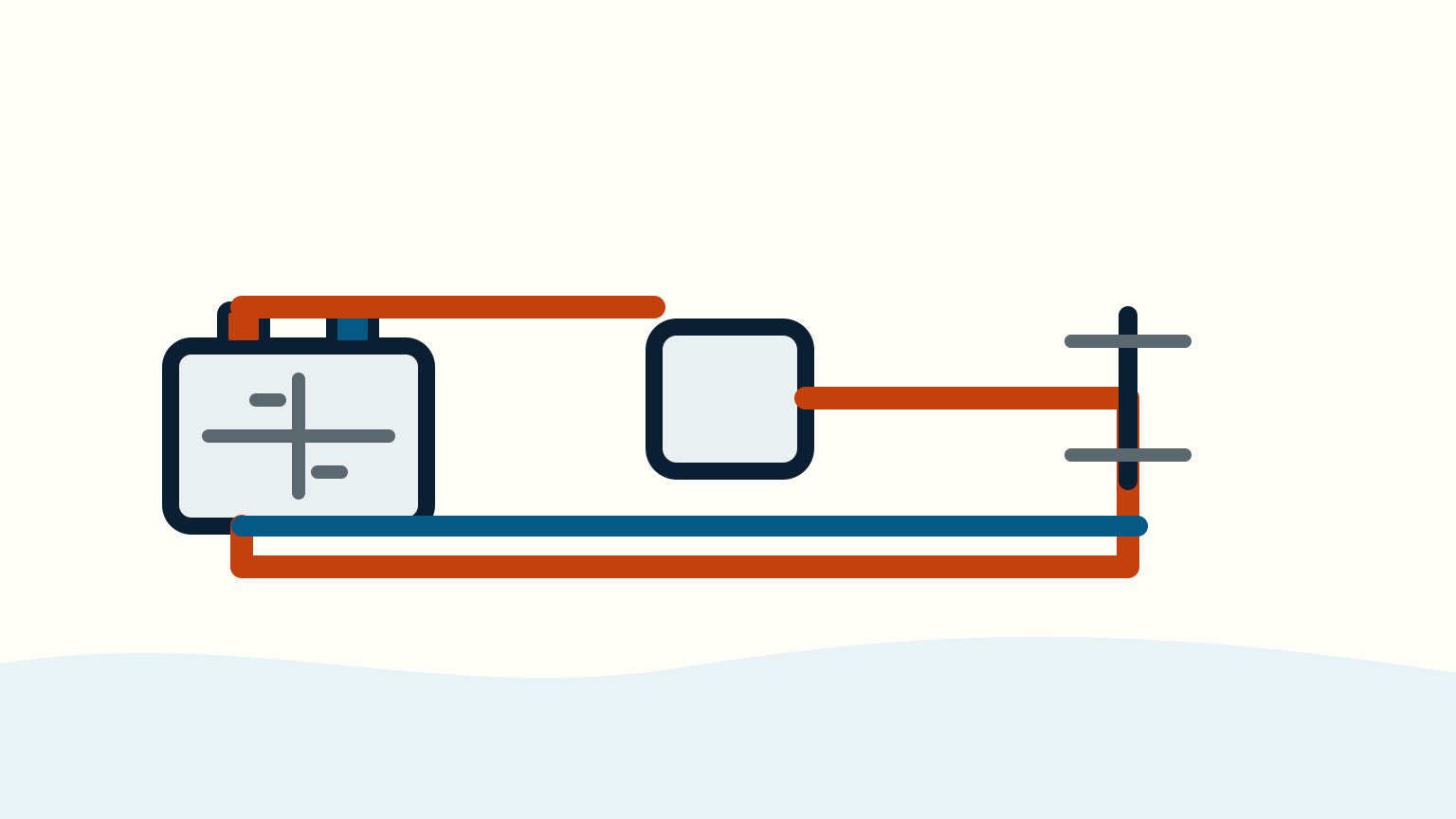
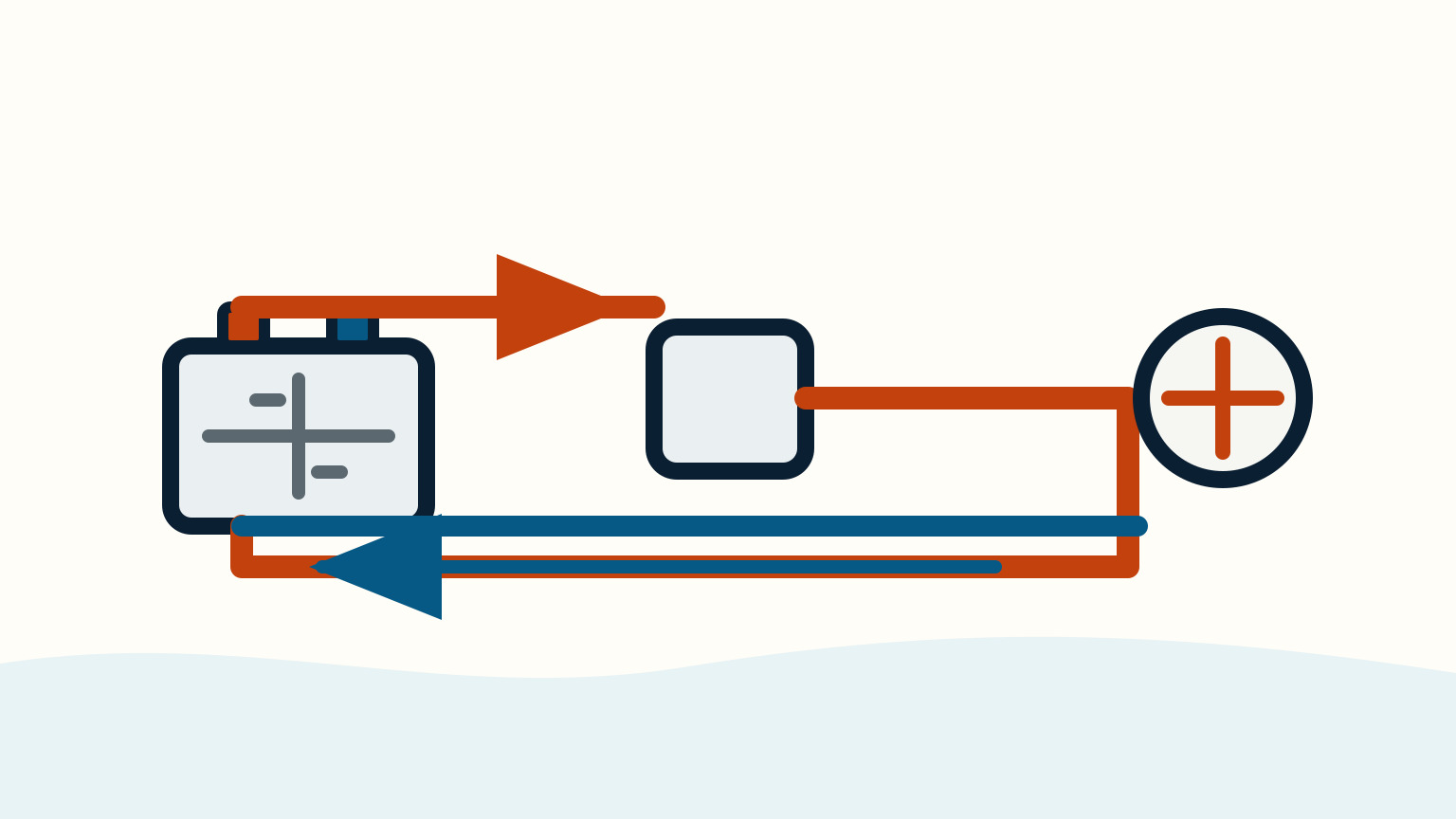
Think of the circuit as a loop, not a one-way wire. Current leaves the source through a protected positive path, travels through the load, and returns through the negative path to the source. The round trip matters. Blue Sea Systems uses the total route from source to load and back when selecting wire for voltage drop. A fault on either side can therefore make the device underperform.
Write down the source reading, load-terminal reading and the exact condition of the load. "Cabin light on" is better than "tested electrical system." If a device changes speed, setting or duty cycle during the reading, note that too. Repeat only when the setup is stable. Numbers without the operating state can point a later technician in the wrong direction.
Prepare A Safe Loaded Test
Use a meter that you understand and leads in sound condition. Read its instructions before bringing it near the boat. Identify the battery or distribution source, the circuit protection, the switch and the load from labels and the boat documentation. Choose exposed test points only if the installed system permits safe access. Never force a probe into a sealed connector or remove a protective cover just to reach a terminal.
Set the boat up so the circuit can be tested in its normal state. A pump test needs water-system conditions that make the pump operate. A lamp test needs the usual lamp. Avoid testing a high-current or safety-critical circuit if you cannot describe its route and safe shutdown. You can learn from a low-risk accessible branch circuit while an electrician handles a starter, windlass, inverter, charging system or unknown panel.
Keep loose metal tools and jewellery away from batteries and live terminals. Protect the meter leads from slipping into adjacent terminals. A battery can supply very high fault current. If the first reading shows unexpected heat, smell, noise or visible damage, turn the circuit off using its intended control and do not continue the test.
Measure Source And Load Voltage
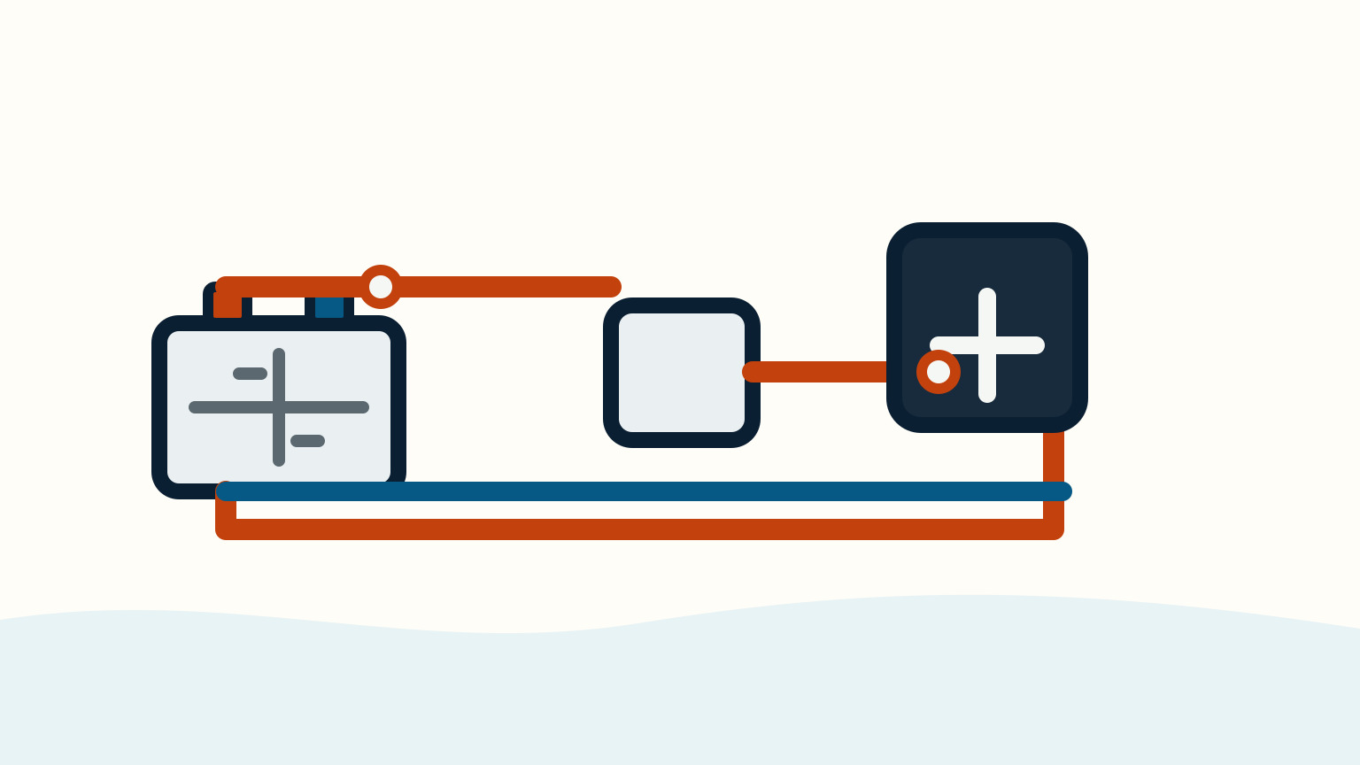
With the load running, measure at the source-side point specified by the boat's documentation and write the result. Then measure at the load terminals, again while the same load is running. Subtract the load reading from the source reading. Do not compare a battery reading taken at rest with a load terminal reading taken under current; that mixes two different conditions.
If source and load readings are close, the problem may be inside the load, in the supply state, or intermittent. If the difference is meaningful, record it and ask where the circuit changes. The next step is not to replace every cable. It is to divide the path into safe, identifiable sections and compare readings across each section under the same load.
The selection target for a circuit depends on its job. Blue Sea Systems describes a 3 percent design basis for critical circuits such as electronics, navigation lights, bilge blowers and panel feeds. It describes 10 percent for non-critical loads. These are design targets, not permission to accept a random loss because a circuit seems non-critical. The conductor must also meet its allowable current rating.
Narrow The Loss By Sections
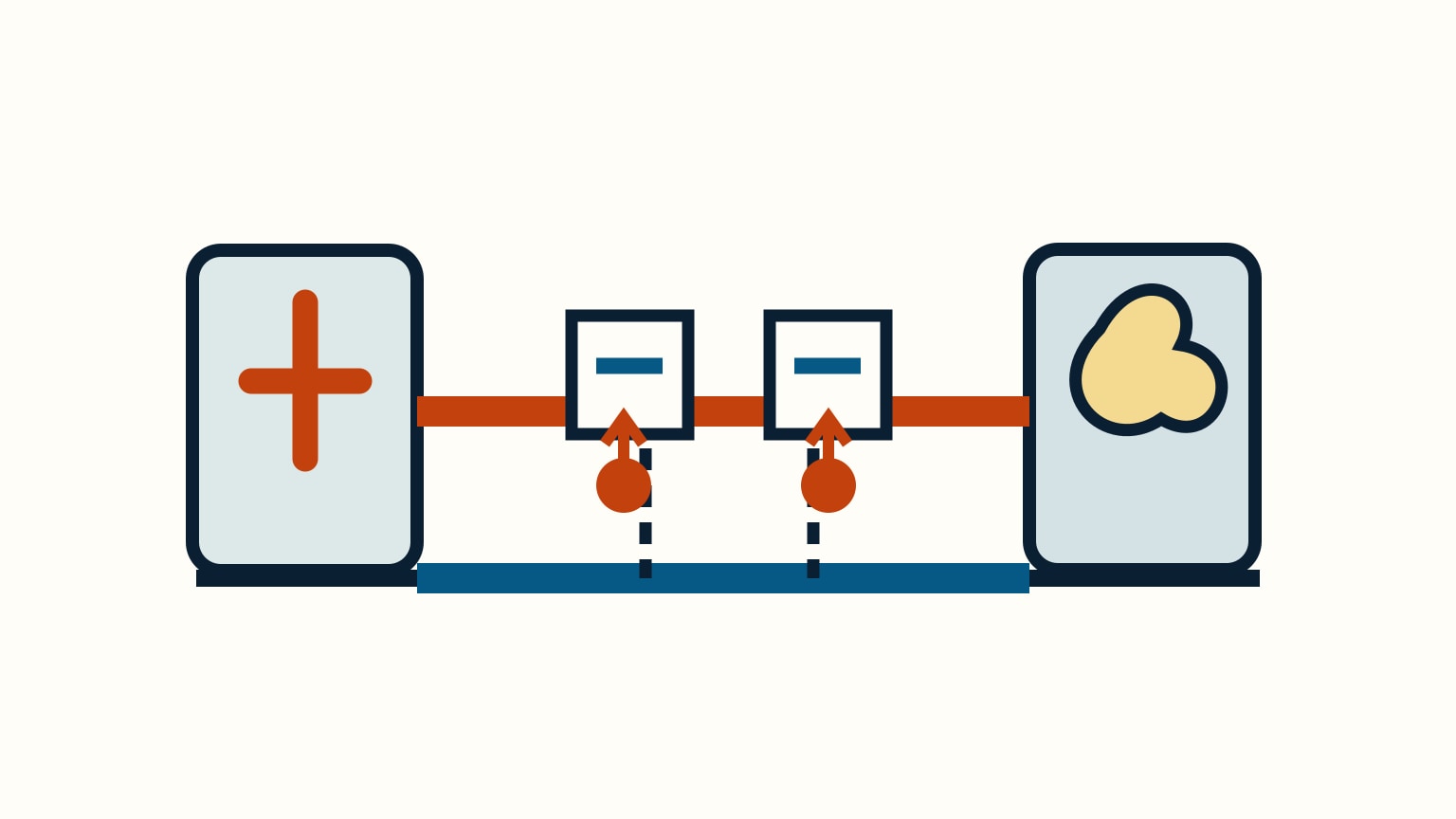
When you can safely identify the route, compare voltage across a single connection or component while the load operates. The goal is to find where the unexpected loss appears, not to turn the meter into a treasure hunt. A fuse holder, breaker, switch, plug, terminal or negative return may be a sensible section only when you know what it is and can reach it without disturbing the circuit.
Look as well as measure. Corrosion, green deposits, loose lugs, heat discoloration, cracked insulation, unsupported wire and water entry are useful observations. They are not a licence to tighten or clean every connection while energized. Photograph the condition and note the test result. A connection can look clean but perform poorly under current, and a dirty connection may not be the only problem.
Stop before a section that includes unfamiliar battery wiring, charging equipment, an inverter, an engine circuit or concealed conductors. A technician can perform voltage-drop tests across the proper components and check torque, cable size, protection and heat damage using the installation requirements. Your record should make that visit shorter, not expand your risk.

Separate Wire Size From Fault Repair
An undersized conductor can cause voltage drop, but so can a poor connection, corroded fuse holder, weak battery, failed switch, damaged load or a route longer than the original design allowed. Cable replacement therefore starts with evidence. Measure the maximum sustained current, determine the complete round-trip length, choose the correct voltage-drop basis for the load, then confirm both voltage-drop and ampacity requirements.
Do not use a larger fuse to compensate for a slow device. Fuses and breakers protect the conductor. Changing protection without a complete conductor and load assessment can remove the thing that limits overheating during a fault. Likewise, adding a random parallel wire or a temporary jumper can create a hidden route that the next person cannot protect or trace.
Tell the technician whether the condition began after a new load, battery change, refit, water intrusion or cable movement. Those events can explain why a formerly adequate circuit no longer performs. Ask for the repaired circuit's measured readings and any new wire-size or protection documentation. Keep that record with the boat's electrical diagram.

Build a useful fault record.
Good fault notes are brief. Record the date, battery condition, charging source state, load tested, source voltage, load voltage, visible symptoms and any heat or corrosion. Include photographs of labels and exterior condition. If the fault is intermittent, record what was different when it occurred: engine running, shore charger connected, wet weather, a particular switch setting or a new appliance.
Use the record to decide whether the boat is safe to operate. A navigation light, bilge blower, communications device or other safety-related circuit that cannot deliver dependable operation deserves urgent professional attention. A non-critical cabin load may allow a more measured inspection, but a damaged or hot connection still needs isolation and repair before it becomes a fire risk.
After repair, repeat the same loaded test in the same conditions. Compare new readings with the original record and confirm that the load operates normally. The result should be a known circuit, not a mystery that happens to work today. Keep the original cause and repair description with the diagram for the next owner or technician.
SailStarter's systems lessons can help you map a boat's DC layout and communicate a fault clearly. Use sailboat battery maintenance, sailboat engine won't start, and shore-power basics for adjacent system clues. They do not replace electrical design, repair, or inspection.
Keep the test leads and meter with the record only if they are clearly identified and in good condition. An unknown lead, damaged insulation, or ambiguous meter setting can create a new electrical hazard during the next check.
Try it from the lesson
Can you spot the next move?
The engine is idling, the boat is safely secured and the propeller area is clear. What should you confirm before departure?
Why you can trust this guide
. We build each guide from public seamanship and safety sources, then teach the universal principle before any local difference.